Corona Classes

It’s been a couple of weeks since the last time I worked in the shop of the school. From the comfortable seat of my house I have been learning CAD, and also have been taking coding classes.

This is my first time working with Motion studies

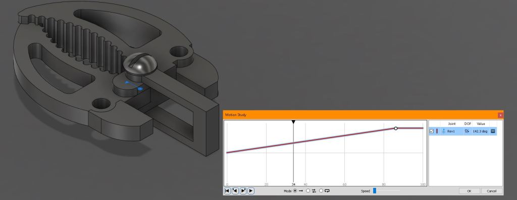
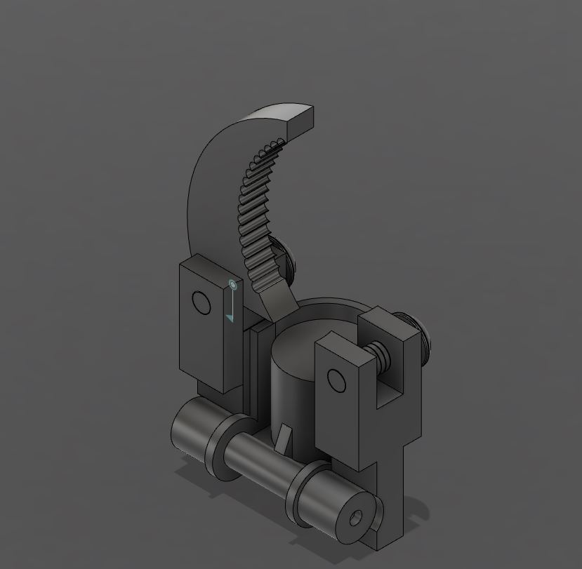
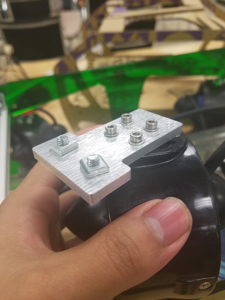
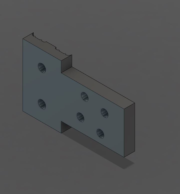
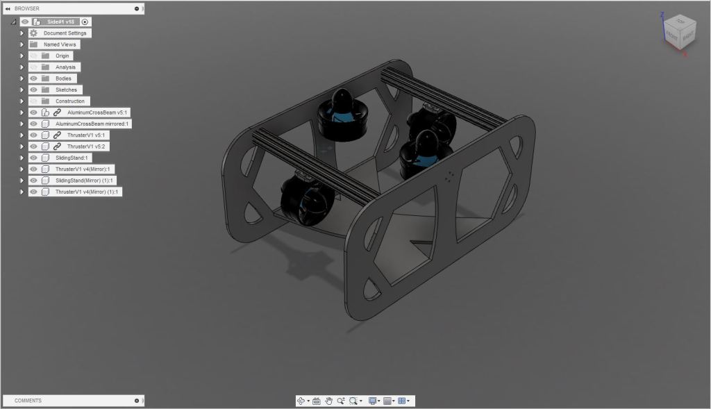
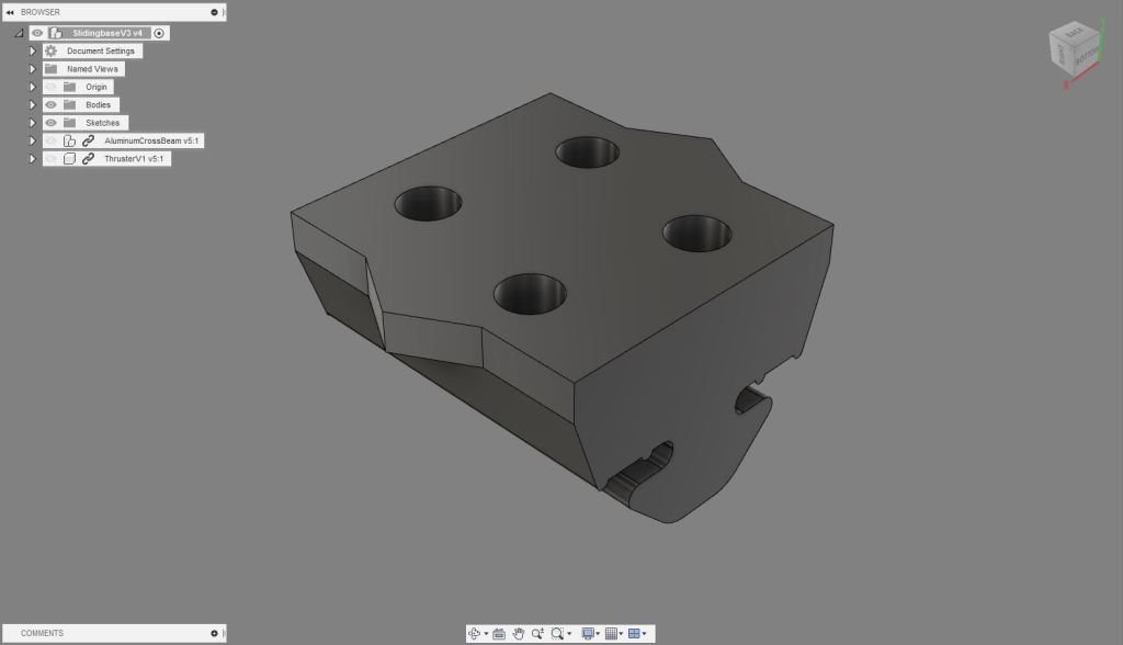
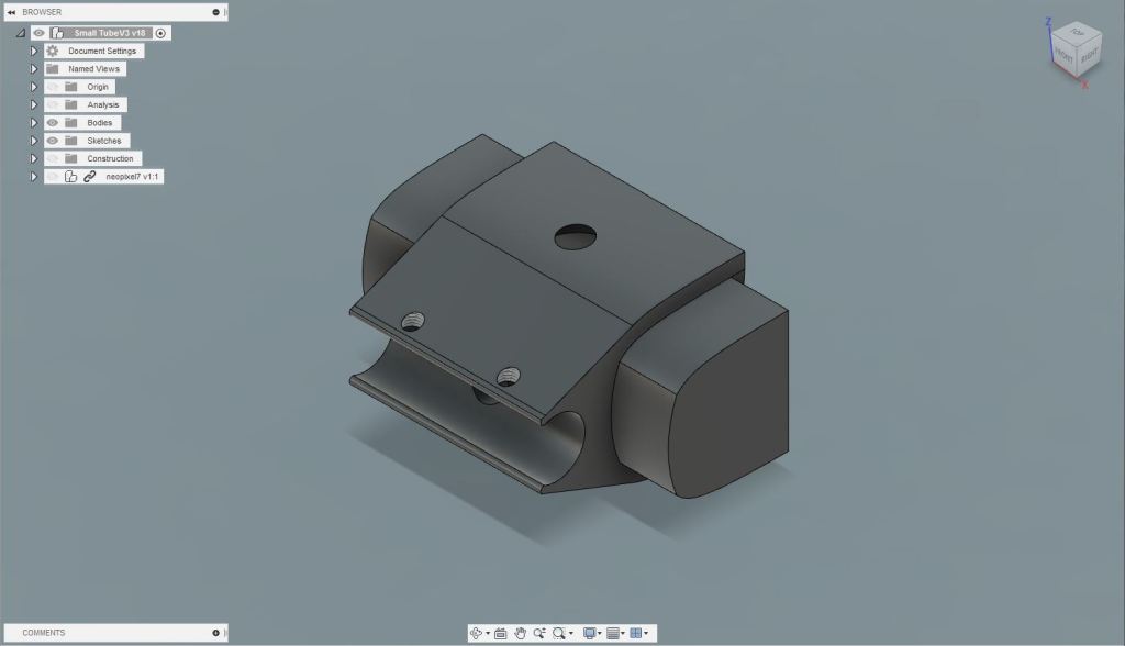
Even thought the design isn’t fully functional yet, the gripper is is getting shaped by the time, and so is the piston that is going to be attached to it eventually.

Square descending

This is the first time I work with JavaScript, the first challenge was to work on a square shape that moves, and so does mine! It is not the most complex code, but it gets the job done. https://www.openprocessing.org/sketch/867855

Working on a Gripper For the S.U.B

This is the first version of the Grippe I’ve designed so far. This is still in an early state, I need to come up with a way to attach the bottom of the gripper to one of the 80/20s. Also this is the first time I am making a functional 3d design, since I don’t how to attach the piston to the claws I have to create a joint I am still learning to use.

Machining Week

Before break I spent a week learning how to work manufacturing in Fusion. This is really amazing as you can tell the machine all the details and different ways you want different pieces to be made. I designed a H standoff to be in between the L brackets an the side panels to prevent damaging components. Also a Aluminum Motor mount to to test the resistance of the material. They look good!

Time to keep designing

S.U.B (newest)

Last week I had a similar design with larger gate 80 by 20 cross beams. This week I’ve been working on fixing the sizes of the S.U.B’s cross beams from 25.40mm to 20mm. The bottom has also been changed, it’s a new concept we hope it works the 80 by 20s holding the tube will hold it in position having straps going around it. This week I hope to be able to laser cup and prepare a 3d model in real life

Let’s keep Designing The SUB

Hey it’s been a week since my last post, and today even though I am a little late with this post I would like to let you know what’s happen during the couple past days. I have been sick, but it hasn’t been a reason to stop me from designing a robots that can house a bunch of circuits inside. Last week I worked with my partner Manny on this new concept to mount the thrusters onto the 80/20s (cross beams), we’ve also modeled the acrylic tube for the circuits, and the side panels conceptV1. To have a better understanding of all the components we came up with a list for all the components and we wanted to see them altogether to have a visualization, there’s still a long way to get somewhere done, but there’s hope!

New design required!

Everything was scheduled to be done by last week. Then many things went wrong…

The housing for the circuit board

The housing for the circuit board finally came to life last week! Then after sanding the inside so the clamp and the box could fit together and testing hole measurements things were looking good. After putting the circuit board inside the box, there was a problem with the wire lengths and also at the back. The hole that goes through the tube, the clamp, and the box seemed to do its job just fine, but then when it came time to plug in the wires from the LED strip to the circuit box there was no easy way to do so… nor a way to.

The new clamp + circuit box housing

It was time to make some changes to the previous design. The new design does have plenty of space now to plug in as many wires as needed from the back easily. Also I decided to add key slots to both ends of the box, now it can easily be mounted onto a wall, and I even added some fillets to the sharp edges.

Design a site like this with WordPress.com
Get started